Handling of Bearing Units
Although NTN's bearing units boast simple handling, inappropriate handling can lead to premature failure of the units. Accidents occurring to bearing units are often caused by improper installation or handling of bearing units. If handled correctly, most accidents can be prevented.
Installation of bearing housing
Pillow block, flange, and stretcher unit take-up
NTN bearing units can be easily installed with a diversity of mounting methods, allowing full design performance to be achieved. When installing them, however, observe the following precautions to ensure that the bearings will work properly for their full design life.
- Bearing housing mounting face must be sufficiently rigid.
- Bearing housing mounting face must be as flat and smooth as possible (when placing the bearing housing on the frame, the housing must be stably seated without any excessive play) (Fig. 1). Flatness:Max. 0.1(0.05 is more useful.) Installing a bearing housing to an uneven frame deforms the bearing housing, causing the bearing to become deformed too, possibly resulting in premature failure of the bearing.
- The tolerance of the angle between the bearing housing mounting face and the shaft should be ±2° max. (for narrower outer ring type, ±1° max.) for convenience of grease injection. For covered units, the tolerance should be ±1° max. (Fig. 2).
- The pillow block type and flange type bearing housings are provided with dowel-pin seats for correct positioning
- Excessive tightening of the mouting bolts may cause the housing to deform. Tightening the bolts to the proper torque can avoid this issue. Also, NTN recommends using a washer with the bolt when mounting the housing as the bolt alone may cause damage to the housing.
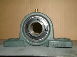
Fig. 1
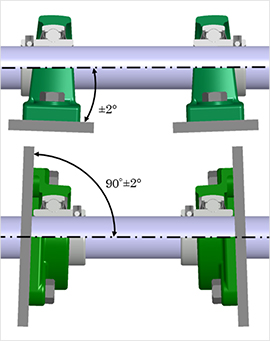
FIg. 2
Cartridge type bearing unit
For normal operating conditions, the cartridge type bearing housing fit must be H7. The housing bore must be finished so that the bearing unit can move freely in the axial direction.
Take-up type bearing unit
To install the take-up type bearing unit, fit the unit in the guide rail on a frame, and secure the inner ring of the bearing to the shaft. Then, install the adjusting bolt and nut, and lock the bearing unit with a tapered pin. Then finally, correctly position the bearing unit.
Installation of set screw type bearing unit
To install the set screw type bearing unit to the shaft, equally tighten two set screws to the recommended torque.
NTN ball-point set screws, having the construction as shown in Fig. 3, are hard to loosen even when subjected to vibrations or impact loads. If fitting clearance between the inner ring and the shaft is small, make a flat (as shown in Fig. 4) approx. 0.2 to 0.5 mm deep on an area of the shaft to which the ball point of the set screw is seated. This arrangement allows the tight-fit bearing to be easily removed from the shaft.
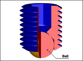
Fig. 3
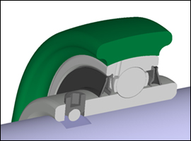
Fig. 4
Install the bearing unit to the shaft
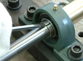
- First, make sure that the set screw does not protrude into the bearing bore.
- Hold the bearing unit with hands squarely to the shaft, and fit it over the shaft straight. Do not turn it. NEVER exert any impact to the bearing unit, nor hit the flinger (Fig. 5).
- Securely install the bearing housing to the specified position of the machines. Recommended torques for tightening hex. head bolt.
Recommended torques for tightening hex. head bolt. - Securely fit an Allen key wrench to the hexagonal socket of a set screw. Then, tighten the two set screws equally with a tightening torque that can be found in Table 2 (Fig. 6).
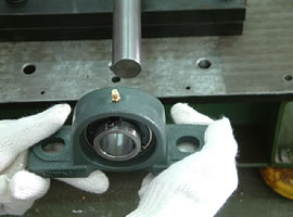
Fig. 5
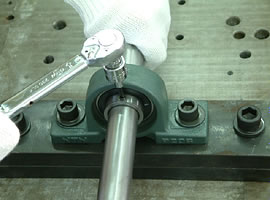
Fig. 6
■How to securely fix the set screw
In the case that impact load is acting on the bearing unit and the unit is operated continuously under relatively high speed (dn = 30,000 and more) and low load (such as only belt tension), it is possible to securely fix the set screw on the shaft by adding the following method.
- After fixing the housing, hit the housing lightly with a wooden or plastic hummer before tightening the set screw. (To prevent “sticking” of the bearing and the shaft)
→ To be done between procedure 3) and 4). - After the test run of the equipment, tighten the set screw further with specified torque as necessary.
→ To be done after procedure 4).
- Set Screw System Unit - (Video)
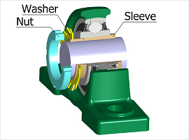
Installation of adapter system unit
The adapter type bearing unit can be reliably secured to the shaft even when it is subjected to impact loads and vibrations. Remember, however, this bearing unit must not be used on a shaft that is subjected to great axial load.
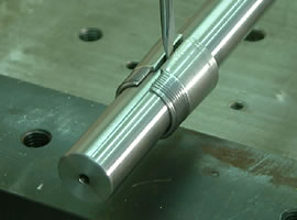
Fig. 7
■Fit the adapter type unit to the shaft
- Fit the sleeve onto the shaft and position it so that its tapered section is roughly centered to the bearing. For easy fitting of the sleeve to the shaft, expand its slot with a flatblade screwdriver. Be sure to install the sleeve so that the nut is positioned opposite to pulley, etc., for easy handling of the bearing unit (Fig. 7).
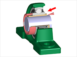
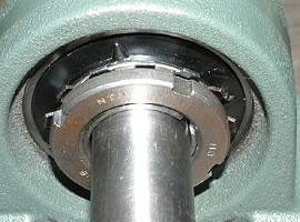
- Fit the bearing unit over the sleeve and fit a cylindrical support, which covers the whole circumference of the bearing's inner ring, to the side face of the bearing's inner ring on the nut side. Then, gently tap the larger diameter side of the sleeve in the arrow mark direction along the whole circumference of the sleeve so that the bearing inner ring is closely seated on the tapered side of the sleeve (Fig. 8 (a)).
- Place the lockwasher, and fully handtighten the nut (Fig. 8 (b)).
- Fit a jig or a screwdriver in one of the slots in the nut, and tap it with a hammer until the nut turns 60° to 90° (NEVER tap the flinger). Overtightening the nut will decrease bearing clearance and deform the inner ring, possibly resulting in overheating or seizing of the bearing. After tightening the nut, check that the shaft can be smoothly turned by hands.
- To lock the nut, bend a tab of the lockwasher that corresponds with a slot on the nut. If necessary, tighten the nut further to align a slot with the lockwasher; NEVER slacken the nut to fit a tab of the lockwasher to the bevel on the nut.
- Securely install the bearing housing to the specified position of the machine.
Recommended torques for tightening hex. head bolt.
- Adapter System Unit - (Video)
Installation of eccentric locking collar system unit
When installing the eccentric collar type bearing unit, tighten the eccentric collar by turning it in the shaft rotating direction to secure the shaft to the inner ring. As a result, the shaft is reliably coupled with the inner ring and virtually no deformation occurs to the inner ring of the bearing. However, this bearing unit is not recommended for the machines which can run forward and backward, since the eccentric collar can loosen.
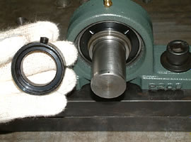
FIg. 9
■Installation of eccentric locking collar type bearing
- Check that the frame is sufficiently rigid and has good flatness for the intended operating conditions where the housing will be mounted.
- Check the shaft end for burrs and confirm that the tip of eccentric collar set screw does not protrude into the bearing bore (Fig. 9).
- Securely install the bearing housing to the frame.
Recommended torques for tightening hex. head bolt. - Correctly position the bearing unit relative to the shaft so the bearing unit is not subjected to axial loads. Then, fit the eccentric collar to the bearing unit.
- Fit the concave side of the eccentric cover over the protrusion provided in the inner ring. Then, turn the eccentric collar in the shaft rotating direction by hands to tighten it temporarily (Fig. 10).
- Fit a rod in the hole on the circumference of the eccentric collar and tap it with a hammer so the collar turns in the shaft rotating direction, as shownin Fig. 11.
- Tighten the eccentric collar set screws to the shaft. The recommended tightening torque can be found in Table 3.
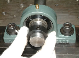
Fig. 10
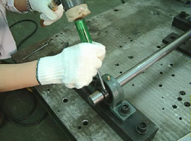
Fig. 11
- Eccentric Collar System Unit - (Video)
Installation of covered bearing units
For covered bearing units, selecting the shaft and fitting the shaft and bearing housing are identical with those for the standard bearing units. The cover can be easily fitted without any special tool or jig.
■Installatin procedure of covered bearing units
- Remove the steel plate cover from the bearing unit. The cover can be easily removed with hands. If it cannot be easily removed, use a screwdriver as shown in Fig. 12.
- To enhance dust and moisture resistance, completely fill the area between the two lips of the rubber seal in the cover with grease. Also, put grease into the cover inside space, to approx. 2/3 its volume (apply cup grease unless otherwise specified) (Fig. 13).
- Chamfer the shaft end to protect the lips of the rubber seal against possible damage. Then, fit the greased cover over the shaft. To do so, fit the inner ring to the shaft, and then tighten the mounting bolts of the housing. Recommended torques for tightening hex. head bolt. The installation procedure sequence may be reversed for convenience in installation (first, tighten the mounting bolts of the housing, and then fit the inner ring to the shaft).
- Fit the cover that is fitted over the shaft, into the spigot of the bearing housing. When fitting the cover, NEVER directly hit it with a steel hammer. First, place a block, made of synthetic resin or wood, over the cover. Then, from 45°direction, tap it with a hammer around the circumference of the cover to exert a uniform impact on the cover to fit it into the groove on the bearing housing (Fig. 14). Fasten the cast iron cover with three set bolts.
- Put grease in the other cover in a manner similar to step 2), and fit the cover over the shaft. If the cover is a closed type, put some grease in advance in the spigot section of the bearing housing (Fig. 13).
- Fit the cover that is fitted over the shaft into the spigot of the bearing housing, in a manner similar to step 4) (Fig. 14).
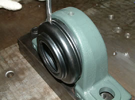
Fig. 12
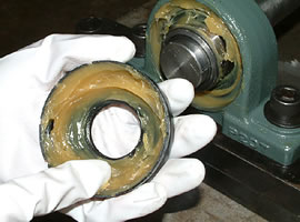
Fig. 13
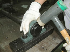
Fig. 14
■Steel plate cover designed for easy installation and removal
- NTN steel plate covered unit has a cover fitting groove as illustrated below (Fig. 15). Fit the cover in the cover fitting groove and tap it with a synthetic resin or wooden hammer from a 45° direction. Then, the cover is securely fitted by reaction force (Fig. 16) (note that #204 is a press-fitted type).
- For easy removal of the cover, a groove is cut on the outer side of the cover. When removing the cover, fit a flatblade screwdriver into this groove, and then pry the cover to remove it. Other manufacturers' bearing covers are all press-fitted, making fitting and removal of covers difficult.
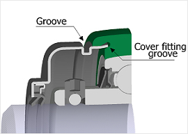
Fig. 15
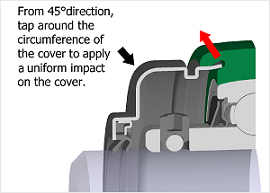
FIg. 16
- Bearing Unit with Steel Plate Covers - (Video)
Removing bearing units
If any problem with the bearing unit necessitates removal and replacement of the bearing, reverse the installation procedure. Before removing the unit, make sure of the following.
■Consider the set screw type
Slacken the set screws, so that the screw point does not scratch on the shaft when removing the unit.
■Consider the adapter type
Straighten the bent tab of the lock washer, and turn back the nut by two or three turns. Then, place a metal block on the nut side face, and tap it with a hammer around the circumference to remove the sleeve (Fig. 17).
NEVER tap the cover if only a portion of nut threading remains engaged. Otherwise, the thread of the nut can be damaged.
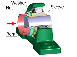
Fig. 17
- Adapter System Unit -
Dismounting the bearing unit from the shaft (Video)